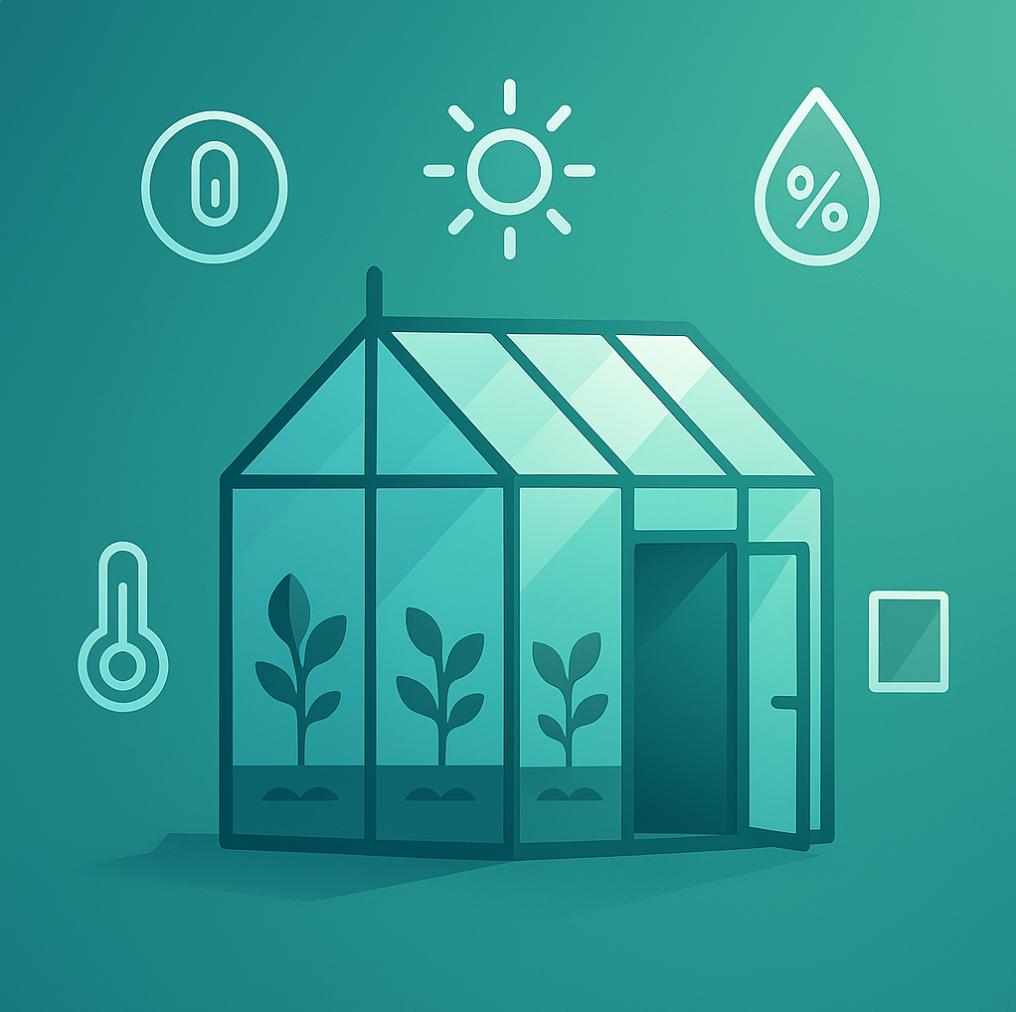
The UK is not really known its extreme weather, but one thing we do know well is unpredictable temperatures and deciding if the wetness will be rain or just the air. After i convinced my better half to want a greenhouse in the garden, my plan was how to make this simple wooden room smart.
You can buy off the shelf to do this, but wheres the fun in that…plus it might not be that compatible with Home Assistant and wheres the fun i buying things that just WORK

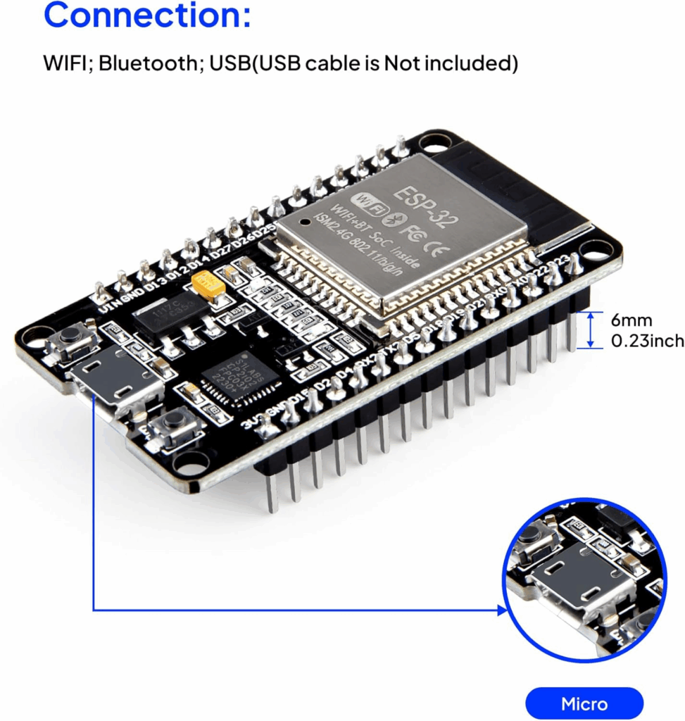
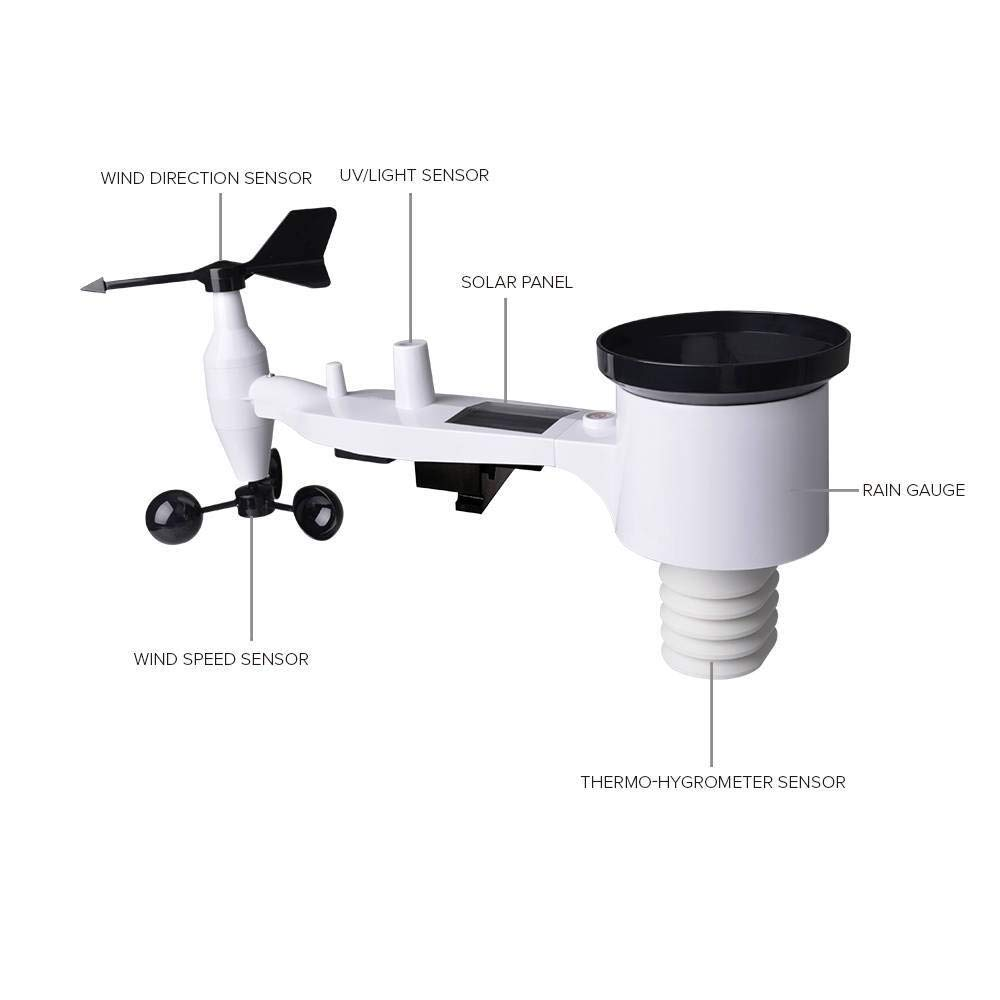
So armed with a few simple components and an ESP32, i set about how to hook this up. As my house is fully setup with homeassistant i already have access to some devices (Outdoor weather station and WIFI Thermometer and Humidity).
The Plan
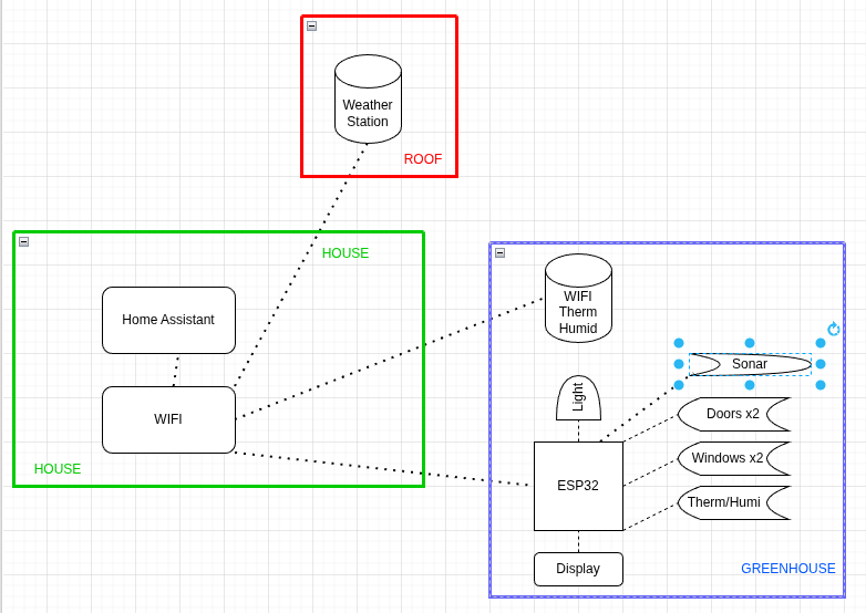
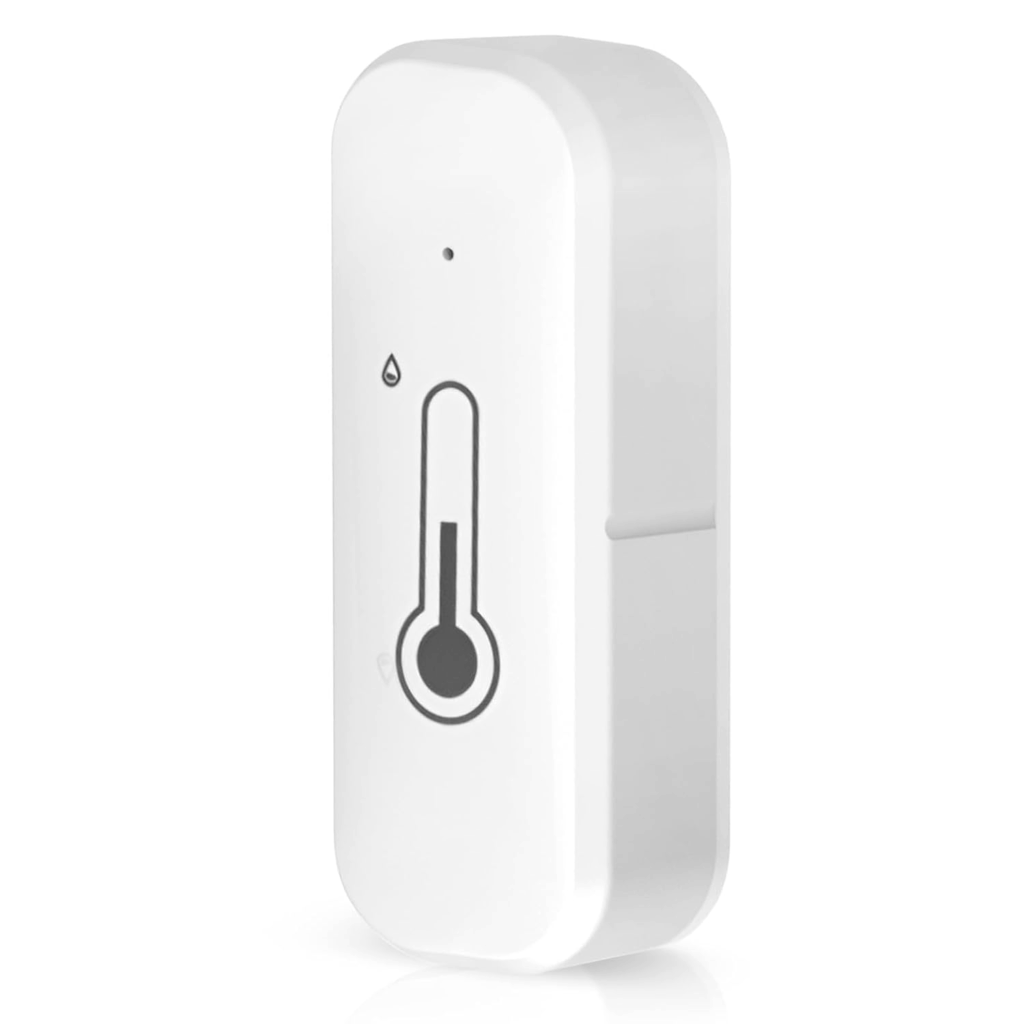
I already have a weather station which reports the outdoor conditions and also a random Tuya wifi Thermometer and Humidity gauge, so i can leverage parts of this to great the basis for an automation setup in there. So my plan was base this on an esp32, hook up a few additional sensors and add a IC2 LCD screen, so i can see the values in the greenhouse.
Sensors
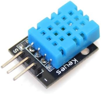
- 2 x Thermometers and Humidity – As I had these kicking about, I planned on using a mix of the wifi/Tuya and the DHT11 sensors (common in Arduino starter kits)
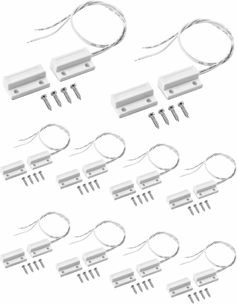
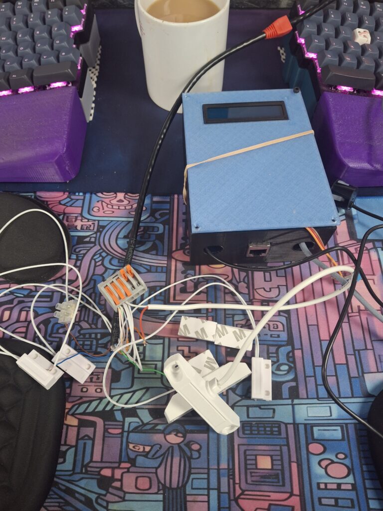
- 4 x Reed switches, so I can track if doors and windows are open
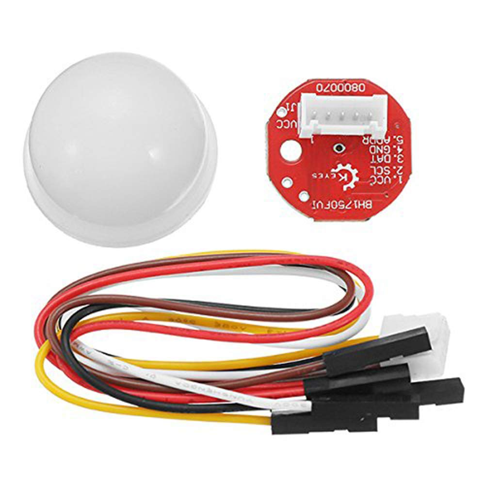
- A LX light sensor, so i can track the light level
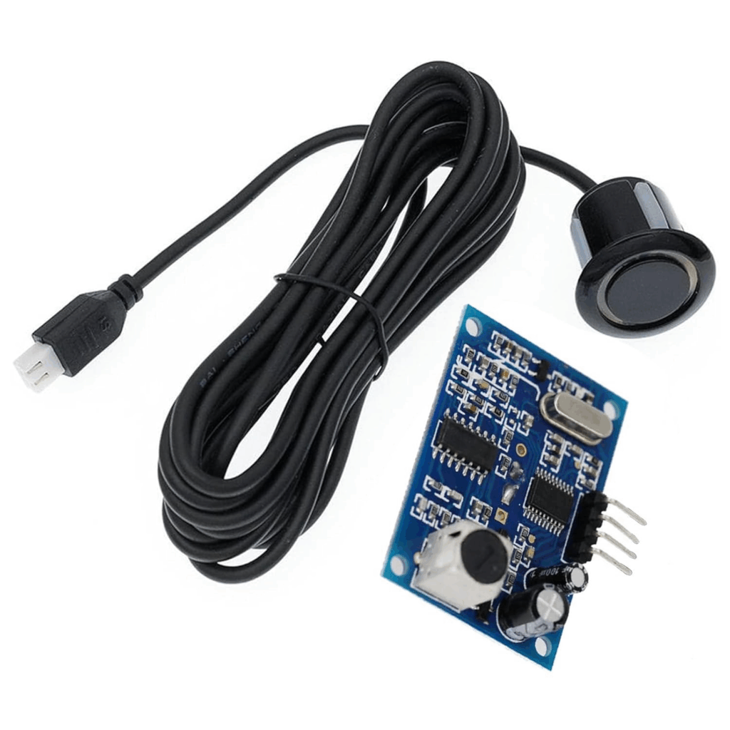
- Sonar distance measurement (for water tank depth)
I planned to use a simple IC2 LCD 2 x 20 Screen, where i could see an overview of the readings.
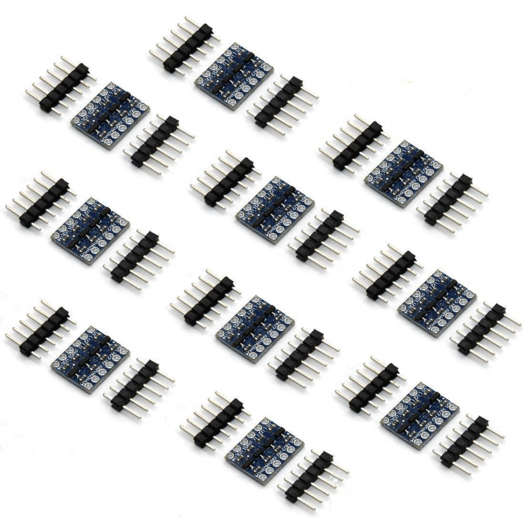
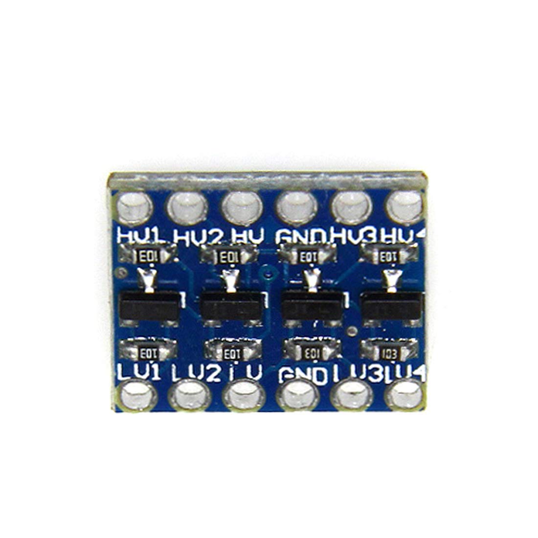
3.3v Device with 5v Sensors/Peripherals
The IC2 screen and Ultrasonic parking sensor all use 5V for power and data, whereas the ESP32 only uses 3.3V. This was something i have not had issue with before, i guess im lucky and use 5V peripherals on Arduino’s. So after a little reading around, i found you can nice little shifters that allow you to run 5v data devices from 3.3v
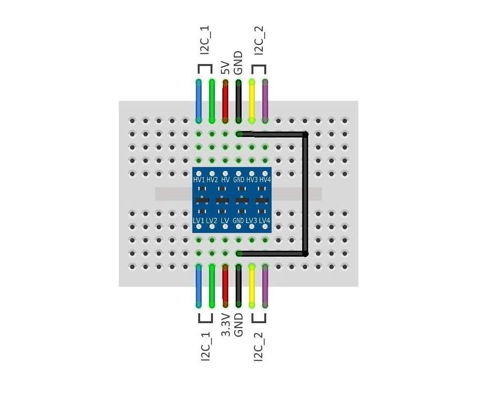
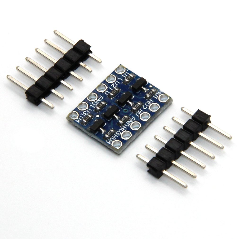
With the screen and ultrasonic, i need 4 data lines and just 1 device was enough to get me passed this.
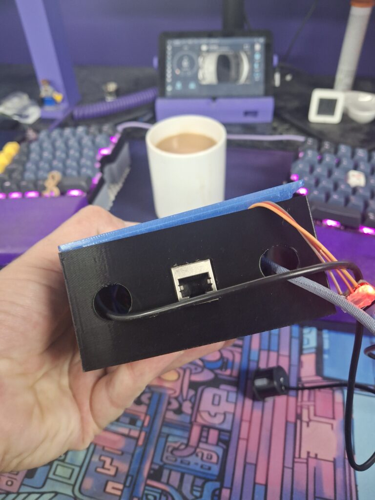
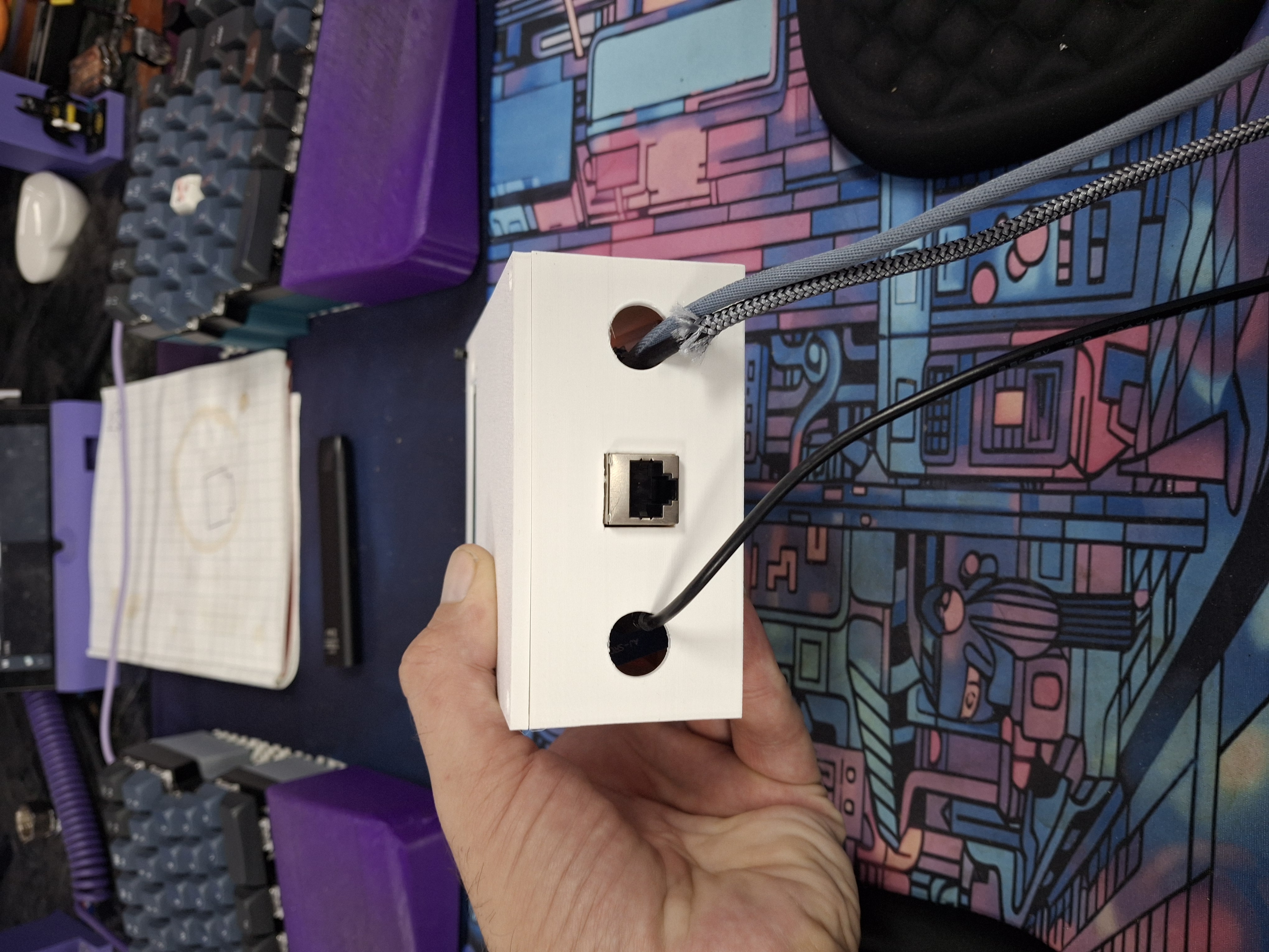
Enclosure
My greenhouse is not exactly outdoor, but even in the UK the range of temperatures it will experience over the year, not mentioning the “dry, arid” environment we have 😂. So I needed a case that will allow us to mount all the peripherals and be attached to a wall inside. So here i opted to create my own, my CAD skills are not exactly amazing, but i get by.
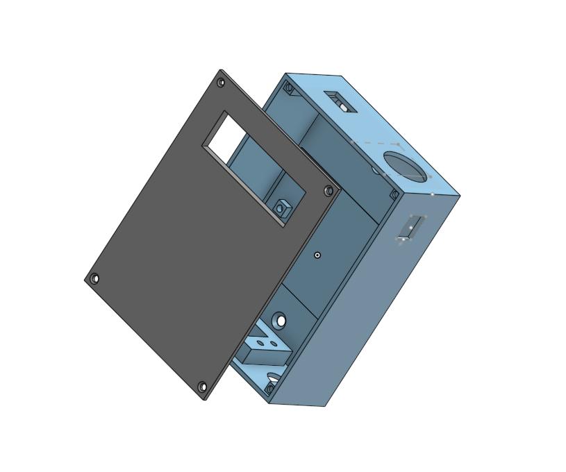
Feel free to reuse the CAD on OnShape
The plans ended here
So with this simple plan in mind, i set about making this work. Sadly I never really planned to blog about this, so I do not have many images.
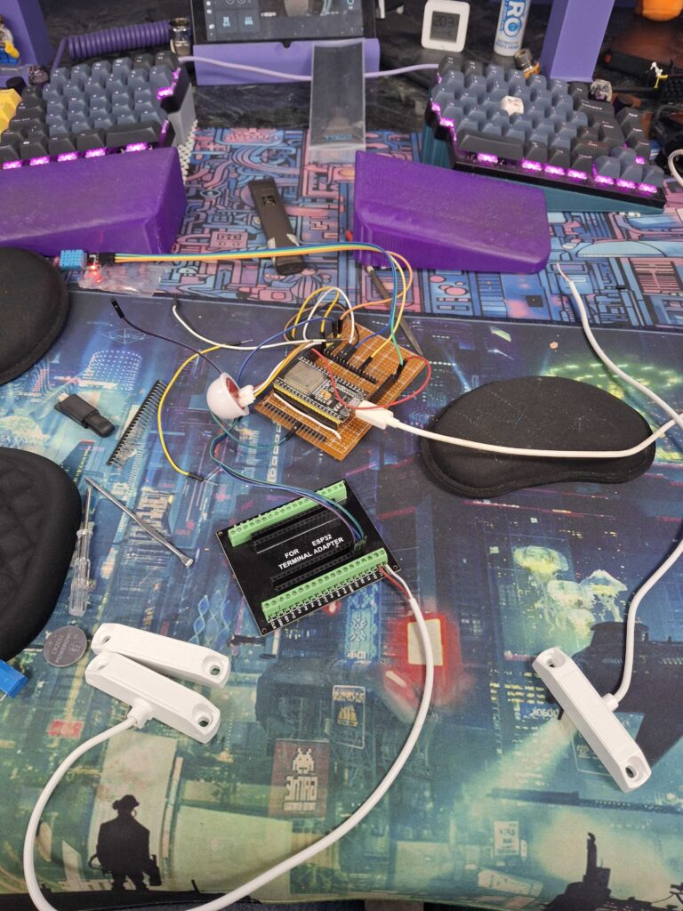
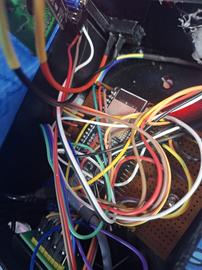
To make this all easier to work with, i created a crude carrier board that allows me to connect jumper cables to all GPIO pins, but with rails for the gnd, 3.3v, 5v and IC2 buses.
The Script
See Code
This is the state of the code as of 25th Sept 2025esphome:
name: xx
friendly_name: xx
esp32:
board: esp32dev
framework:
type: arduino
# Enable logging
logger:
i2c:
sda: 21
scl: 22
scan: true # helps confirm the address in logs
frequency: 100kHz
# Enable Home Assistant API
api:
encryption:
key: "xx"
ota:
- platform: esphome
password: "xx"
wifi:
networks:
- ssid: !secret xx
password: !secret xx
- ssid: !secret xx
password: !secret xx
- ssid: !secret xx
password: !secret xx
# Enable fallback hotspot (captive portal) in case wifi connection fails
ap:
ssid: "xx"
password: "xx"
manual_ip:
static_ip: 192.xx.xx.xx
gateway: 192.xx.xx.1
subnet: 255.255.255.0
captive_portal:
binary_sensor:
- platform: status
name: "Statussensor"
id: statussensor_ghouse_node
- platform: gpio
id: win1
name: "Window 1"
device_class: window
pin:
number: GPIO13
mode:
input: true
pullup: true
filters:
- delayed_on: 20ms
- delayed_off: 20ms
- platform: gpio
id: win2
name: "Window 2"
device_class: window
pin:
number: GPIO14
mode:
input: true
pullup: true
filters:
- delayed_on: 20ms
- delayed_off: 20ms
- platform: gpio
id: door1
name: "Door 1"
device_class: door
pin:
number: GPIO25
mode:
input: true
pullup: true
filters:
- delayed_on: 20ms
- delayed_off: 20ms
- platform: gpio
id: door2
name: "Door 2"
device_class: door
pin:
number: GPIO26
mode:
input: true
pullup: true
filters:
- delayed_on: 20ms
- delayed_off: 20ms
number:
- platform: template
id: tank_depth_m
name: "Tank Depth (m)"
min_value: 0.50
max_value: 2.00
step: 0.01
initial_value: 0.90
optimistic: true
entity_category: config # (optional) shows under "settings" in HA
- platform: template
id: tank_diameter_m
name: "Tank Diameter (m)"
min_value: 0.20
max_value: 0.60
step: 0.01
initial_value: 0.38
optimistic: true
entity_category: config # (optional)
globals:
- id: page
type: int
restore_value: no
initial_value: '0'
interval:
- interval: 5s
then:
- lambda: |-
id(page) = (id(page) + 1) % 5; // change to % 4 when you add a 4th screen
id(lcd).update(); // refresh immediately
sensor:
# --- BH1750 ---
- platform: bh1750
id: lux # <-- ID defined here
name: "Greenhouse Light"
address: 0x23
update_interval: 10s
# --- DHT11 ---
- platform: dht
model: DHT11
pin:
number: GPIO4
mode: INPUT_PULLUP
temperature:
id: temp # <-- ID defined here
name: "Greenhouse ESP32 Temperature"
humidity:
id: humid # <-- ID defined here
name: "Greenhouse ESP32 Humidity"
update_interval: 60s
- platform: ultrasonic
id: water_distance
name: "Water Distance"
trigger_pin: GPIO18
echo_pin: GPIO19
update_interval: 10s
timeout: 3m # ignore anything farther than ~3 m
filters:
# Keep readings sane; AJ/JSN-style sensors can glitch near min range
- lambda: |-
if (x < 0.05 || x > 3.0) return NAN; // ignore <5 cm or >3 m
return x;
- median:
window_size: 7
send_every: 3
send_first_at: 3
# --- Water level height (cm) ---
- platform: template
id: water_level_cm
name: "Water Level"
unit_of_measurement: "cm"
accuracy_decimals: 0
update_interval: 10s
lambda: |-
if (!id(water_distance).has_state()) return NAN;
const float depth = id(tank_depth_m).state; // m
float d = id(water_distance).state; // m
float level = depth - d; // m
if (level < 0) level = 0;
if (level > depth) level = depth;
return level * 100.0f; // cm
state_class: measurement
device_class: distance
# --- Water percent ---
- platform: template
id: water_percent
name: "Water Percent"
unit_of_measurement: "%"
accuracy_decimals: 0
update_interval: 10s
lambda: |-
if (!id(water_distance).has_state()) return NAN;
const float depth = id(tank_depth_m).state;
float level = depth - id(water_distance).state;
if (level < 0) level = 0;
if (level > depth) level = depth;
return depth > 0 ? (level / depth) * 100.0f : NAN;
state_class: measurement
# --- Water volume (L) assuming a cylinder ---
- platform: template
id: water_liters
name: "Water Volume"
unit_of_measurement: "L"
accuracy_decimals: 0
update_interval: 10s
lambda: |-
if (!id(water_distance).has_state()) return NAN;
const float depth = id(tank_depth_m).state; // m
float level = depth - id(water_distance).state; // m
if (level < 0) level = 0;
if (level > depth) level = depth;
const float r = id(tank_diameter_m).state / 2.0f; // m
const float vol_m3 = 3.14159265f * r * r * level;
return vol_m3 * 1000.0f; // L
state_class: measurement
# --- HA mirrors (read-only from Home Assistant) ---
- platform: homeassistant
id: ha_temp
entity_id: sensor.greenhouse_temp_temperature
internal: true
- platform: homeassistant
id: ha_hum
entity_id: sensor.greenhouse_temp_humidity
internal: true
# --- Outdoor station from Home Assistant ---
- platform: homeassistant
id: out_temp
entity_id: sensor.weathersen_outdoor_temp
internal: true
- platform: homeassistant
id: out_hum
entity_id: sensor.weathersen_outdoor_humidity
internal: true
text_sensor:
# --- Forecast (text) ---
- platform: homeassistant
id: wx3h
entity_id: sensor.met_office_kirkby_in_ashfield_weather_3_hourly
internal: true
# --- Sun state + next events ---
- platform: homeassistant
id: sun_state
entity_id: sun.sun
internal: true
- platform: homeassistant
id: sun_next_set
entity_id: sun.sun
attribute: next_setting
internal: true
- platform: homeassistant
id: sun_next_rise
entity_id: sun.sun
attribute: next_rising
internal: true
display:
- platform: lcd_pcf8574
id: lcd
dimensions: 16x2
address: 0x27
update_interval: 1s
lambda: |-
switch (id(page)) {
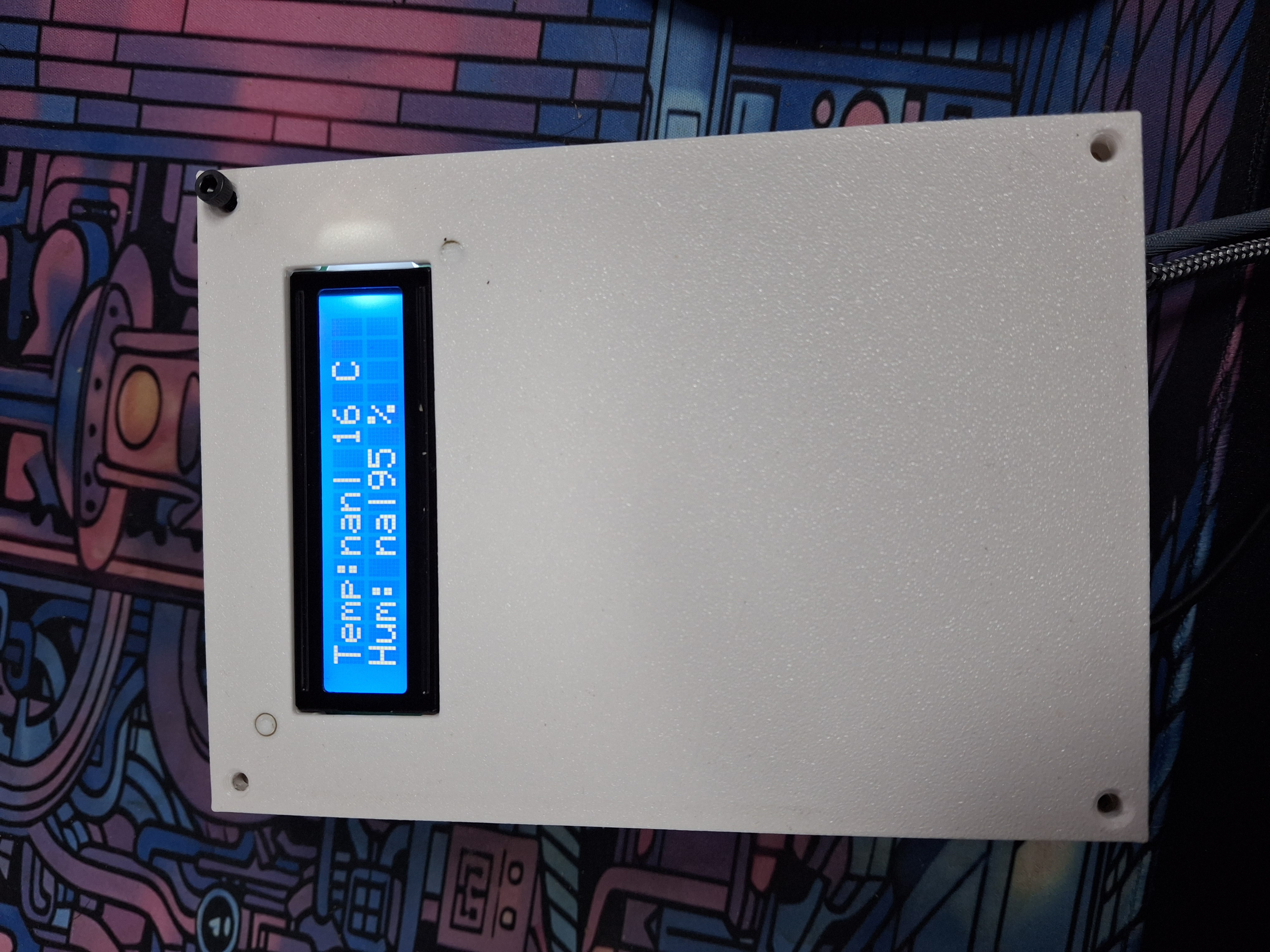
// -------- 1: Temp & Hum (local | HA), fixed width --------
case 0: {
char t_loc[4] = " --";
char t_ha [4] = " --";
char h_loc[3] = "--";
char h_ha [3] = "--";
if (id(temp).has_state()) snprintf(t_loc, sizeof(t_loc), "%3.0f", id(temp).state);
if (id(ha_temp).has_state()) snprintf(t_ha, sizeof(t_ha), "%3.0f", id(ha_temp).state);
if (id(humid).has_state()) snprintf(h_loc, sizeof(h_loc), "%2.0f", id(humid).state);
if (id(ha_hum).has_state()) snprintf(h_ha, sizeof(h_ha), "%2.0f", id(ha_hum).state);
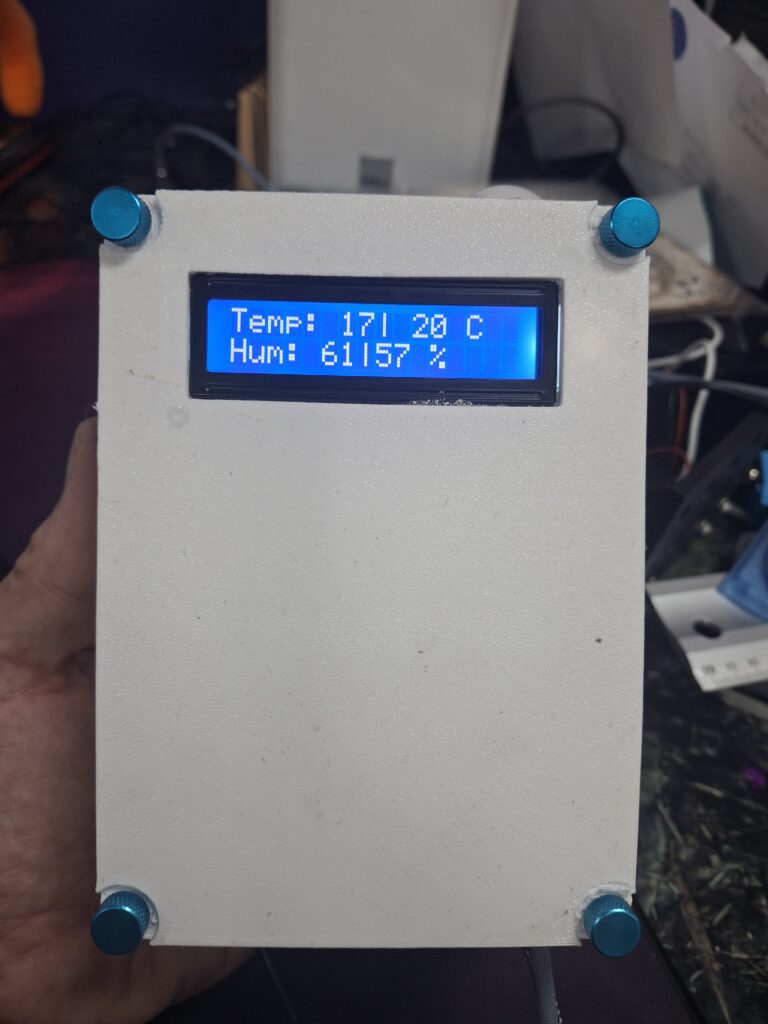
it.printf(0, 0, "Temp:%s|%s C", t_loc, t_ha); // 14 chars total
it.printf(0, 1, "Hum: %s|%s %%", h_loc, h_ha); // 12 chars
break;
}
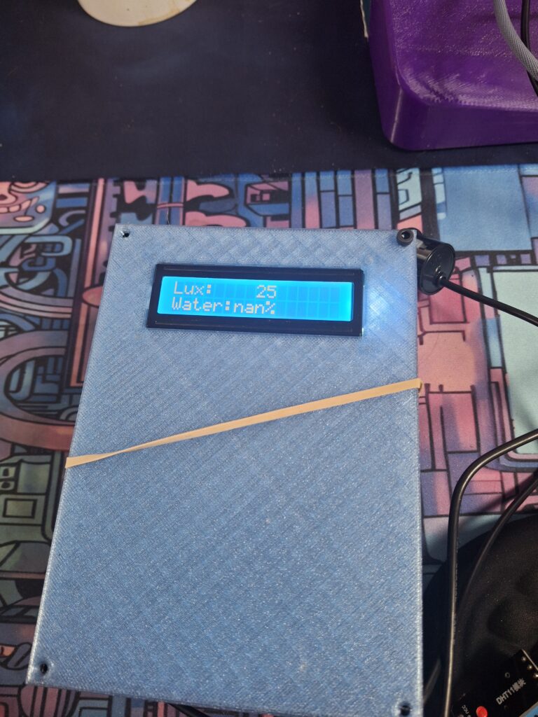
// -------- 2: Lux & Water placeholder --------
case 1: { // Screen 2: Lux & Water
if (id(lux).has_state()) it.printf(0, 0, "Lux:%6.0f", id(lux).state);
else it.print (0, 0, "Lux: --");
if (id(water_percent).has_state()) {
it.printf(0, 1, "Water:%3.0f%%", id(water_percent).state); // e.g. "Water: 75%"
} else {
it.print(0, 1, "Water: --");
}
break;
}
// -------- 3: Windows/Doors (O=open, C=closed) --------
case 2: {
char w1 = '-', w2 = '-';
char d1 = '-', d2 = '-';
if (id(win1).has_state()) w1 = id(win1).state ? 'O' : 'C';
if (id(win2).has_state()) w2 = id(win2).state ? 'O' : 'C';
if (id(door1).has_state()) d1 = id(door1).state ? 'O' : 'C';
if (id(door2).has_state()) d2 = id(door2).state ? 'O' : 'C';
it.printf(0, 0, "W1:%c W2:%c", w1, w2);
it.printf(0, 1, "D1:%c D2:%c", d1, d2);
break;
}
// -------- 4: Met + Me --------
// Line0: "Met: {weather}" → we trim to 11 chars so "Met: "+11 fits 16
// Line1: "Me: ttt | hh" → ttt is -dd/ dd ; hh is dd
case 3: {
std::string wx = id(wx3h).state;
if (wx.empty()) wx = "--";
for (auto &c : wx) if (c == '_') c = ' '; // prettier than underscores
if (wx.size() > 11) wx = wx.substr(0, 11);
it.printf(0, 0, "Met: %s", wx.c_str());
char t_me[4] = " --";
char h_me[3] = "--";
if (id(out_temp).has_state()) snprintf(t_me, sizeof(t_me), "%3.0f", id(out_temp).state);
if (id(out_hum).has_state()) snprintf(h_me, sizeof(h_me), "%2.0f", id(out_hum).state);
it.printf(0, 1, "Me: %s | %s", t_me, h_me);
break;
}
// -------- 5: Next Sun event --------
// Line0: "Sunset" or " Sunrise"
// Line1: "HH:MM"
case 4: {
std::string label = " Sunset";
std::string ts = " --:--";
if (id(sun_state).state == "above_horizon") {
const auto &s = id(sun_next_set).state;
if (s.size() >= 16) ts = s.substr(11, 5); // HH:MM from ISO
label = " Sunset";
} else {
const auto &s = id(sun_next_rise).state;
if (s.size() >= 16) ts = s.substr(11, 5);
label = " Sunrise";
}
it.print(0, 0, label.c_str());
it.print(0, 1, ts.c_str());
break;
}
}
This script basically gets all the details and then displays them over 5 screens, along with additional data from homeassistant. Nothing really complex in there, the display was the most frustrating part to do and as you can see, i resorted to Cursor (AI) to get it finished.
States/Entities Used
- Outdoor temperature (from weather station via Homeassistant)
- Outdoor humidity (from weather station via Homeassistnat)
- 1 word weather forecast (from Met Office via Homeassistnat)
- WiFi temperature (From Tuya via Homeassistnat)
- Wifi humidity (From Tuya via Homeassistnat)
- Next sunset (From Homeassistant)
- Device temperature (from DHT11 sensor)
- Device humidity (from DHT11 sensor)
- Water depth (from SR04T sensor)
- Water width (from SR04T sensor)
- Water volume (from SR04T sensor)
- Water % (from SR04T sensor)
- Water tank depth (from Homeassistant)
- Water tank width (from Homeassistant)
- Window 1 (Reed Switch)
- Window 2 (Reed Switch)
- Door 1 (Reed Switch)
- Door 2 (Reed Switch)
The way we make the water level work, is we use the tank depth and width values (set in HA) to try and estimate the amount of water we have.
Builds
What follows now is reports from builds and the issues that arise and revisions that follow
September 25th 2025
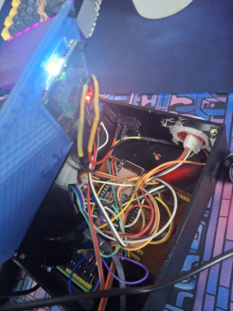
After a few trial runs with the case, i finally got it all in the case and wired up. Didnt connect the window/door sensors (did for video), but enough for a trial run (even made a homeassitant dashboard).
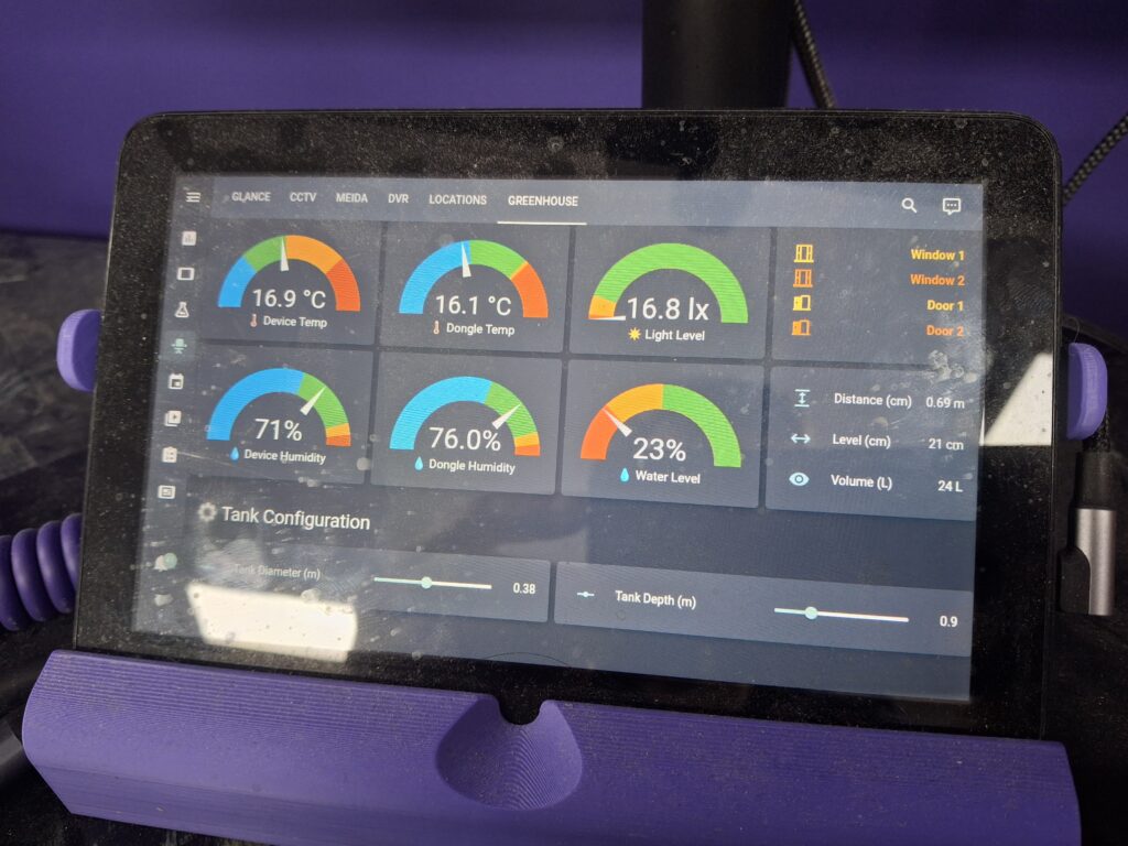
its not pretty, but it was enough to see it in action.
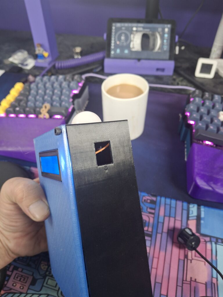
I did have some issues as i mention in the video, mostly the case is black so once the sun comes out, it soon warms up and even today in late September, it hit 50C reading. So the next plan is a white case, and to put the sensor in a Stevenson screen housing on a cable, so i can mount that away from the case and walls etc.
-
After the initial overheating issues, i made a few changes that will help moving forwards.
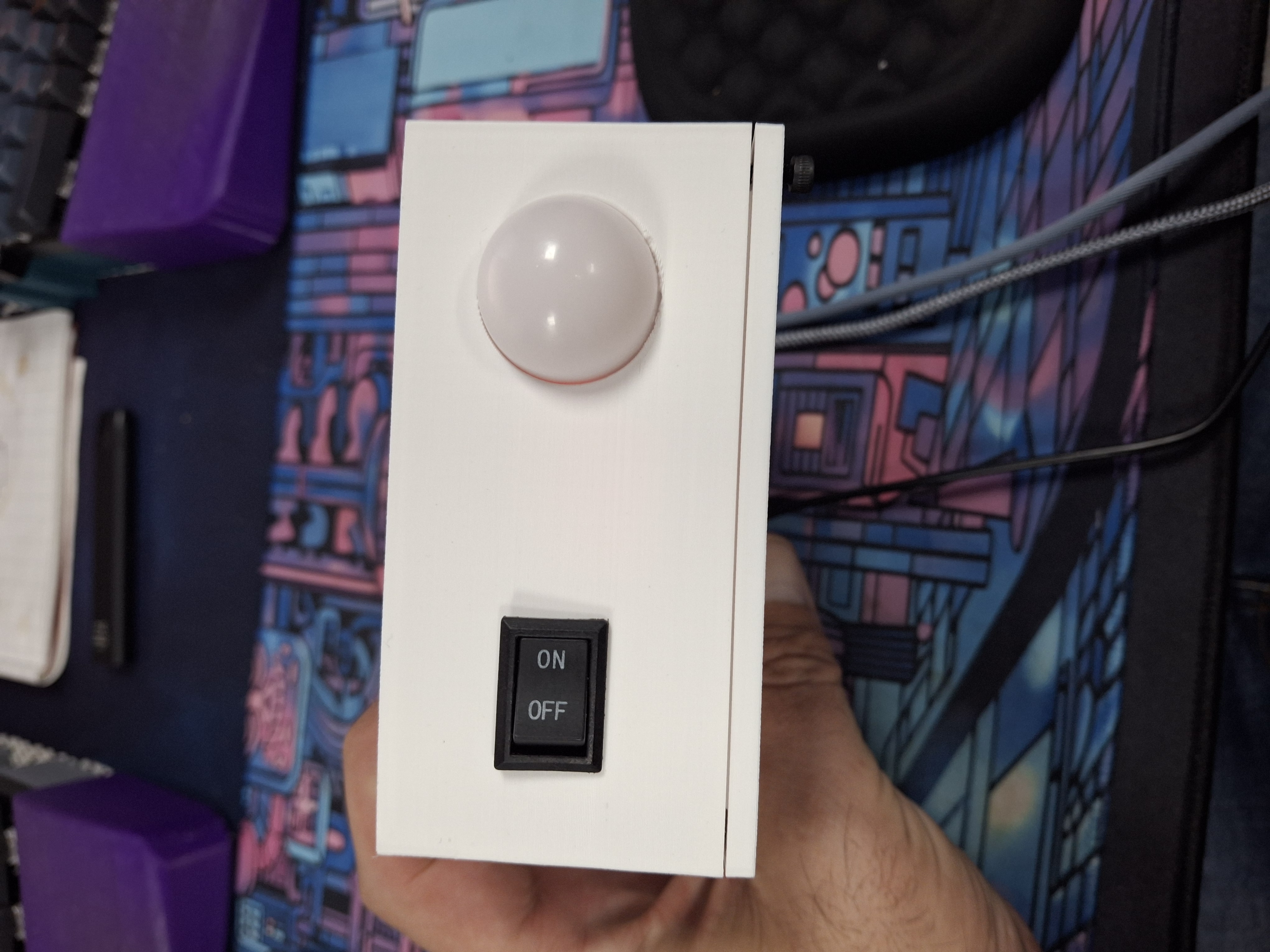
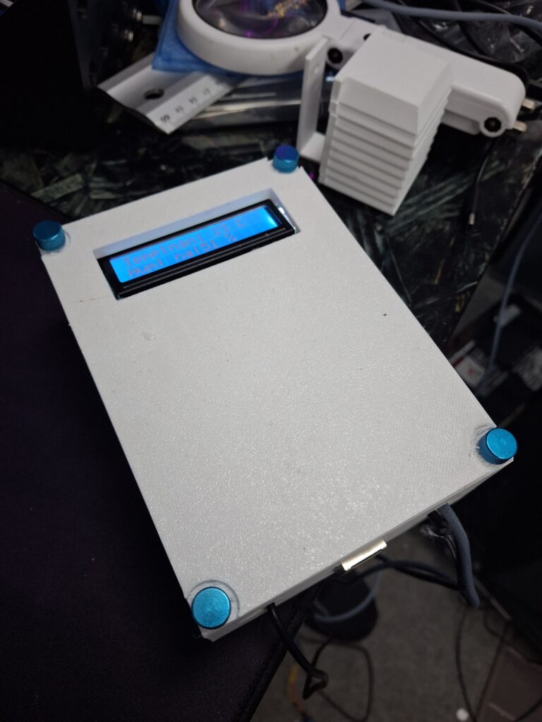
- The case is now matt white, to try and reflect some of the heat
- I have moved the DHT11 from the side of the case, to inside its own Stevenson shield
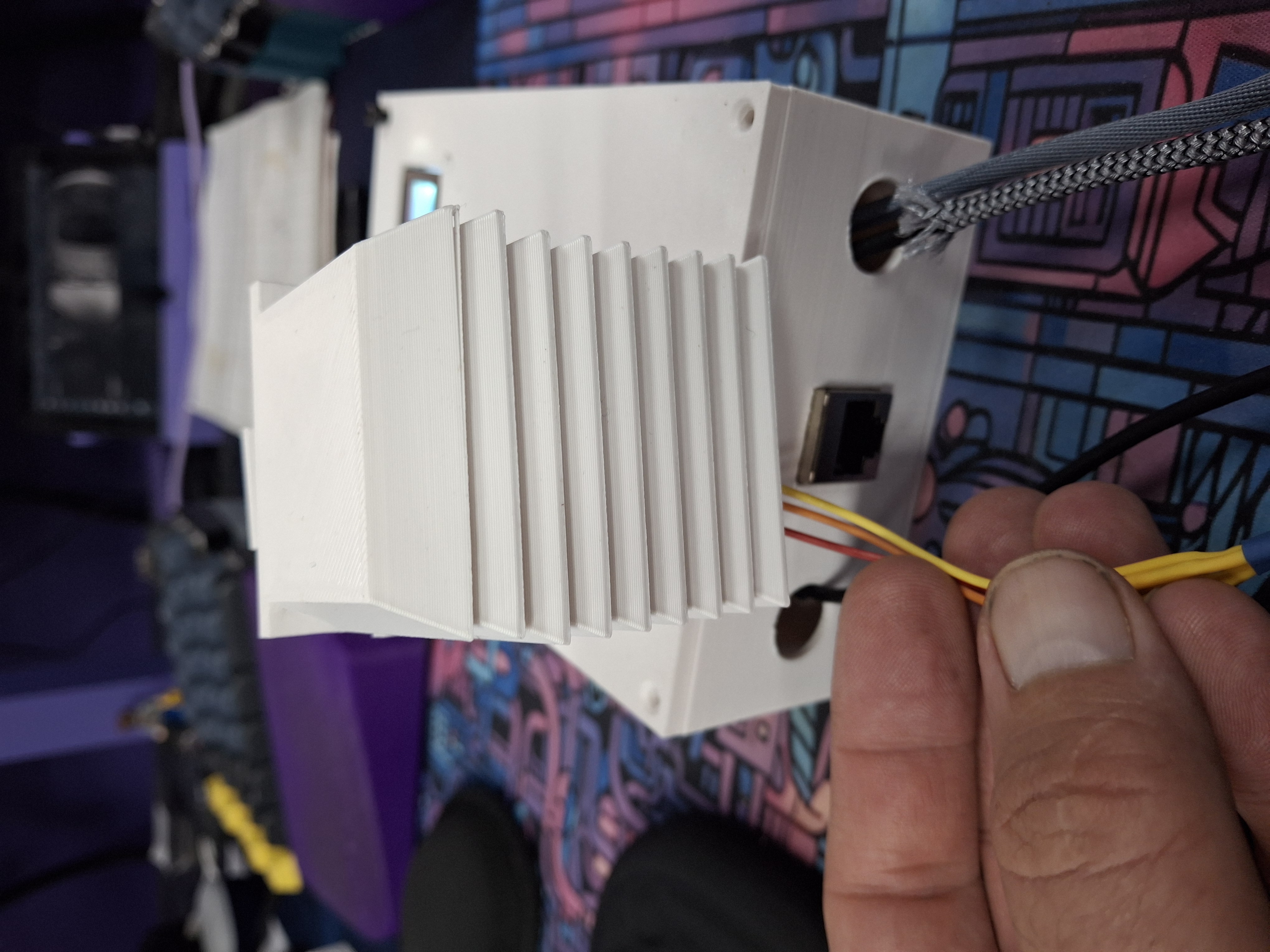
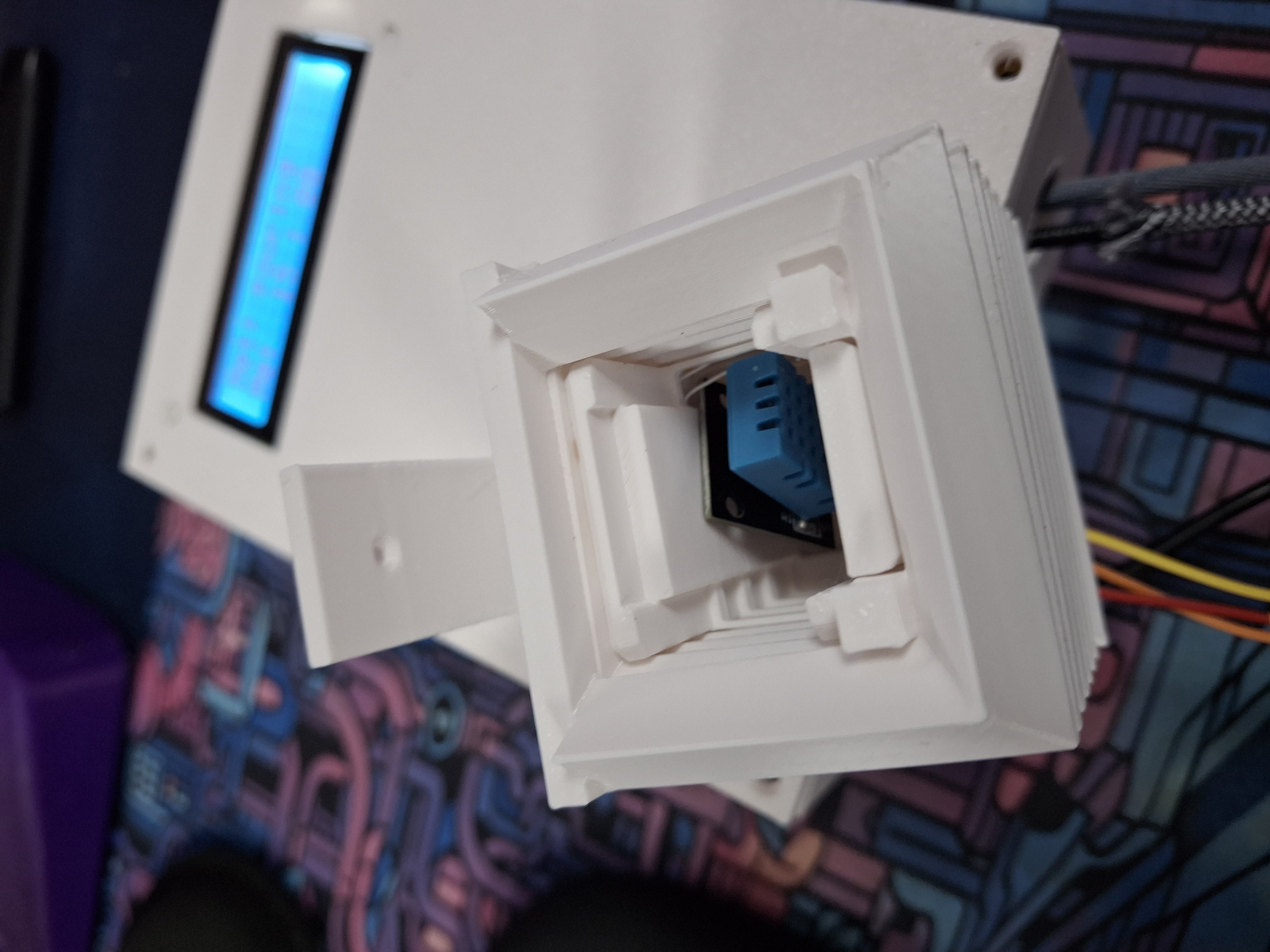
The Stevenson Shield was found on Thingiverse, big thanks to TheChay for sharing that. I created a simple bracket to mount it and this now uses 8x smaller plates and the top. The top will need to be glued to the 1st plate and the sensor it self, should be stuck inside with a foam sticker
-
I needed some nice screws to to put the lid on with, as i suspect i will need to access this a few more times, i opted to get some nice finger screws…..Found some really nice blue ones, the would look so good on the white
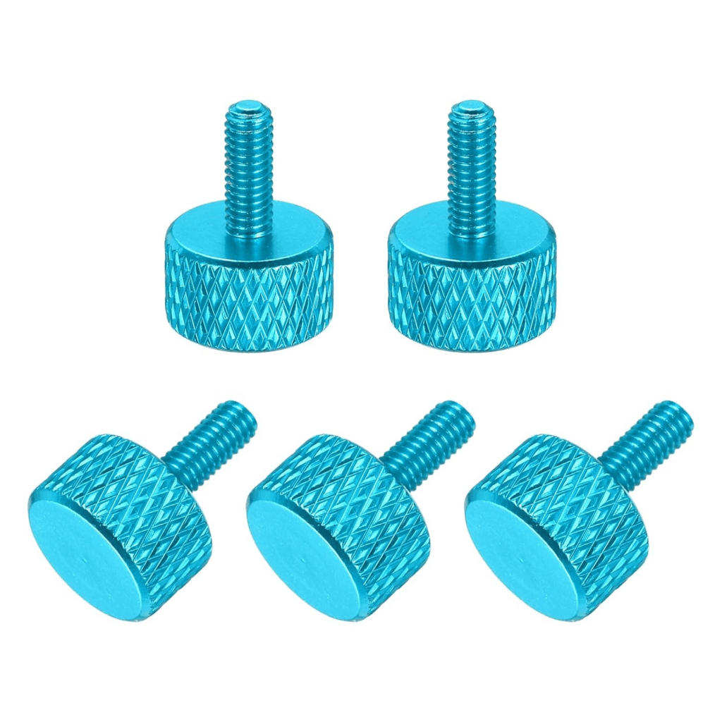
I mean look at them, lovely!!!!
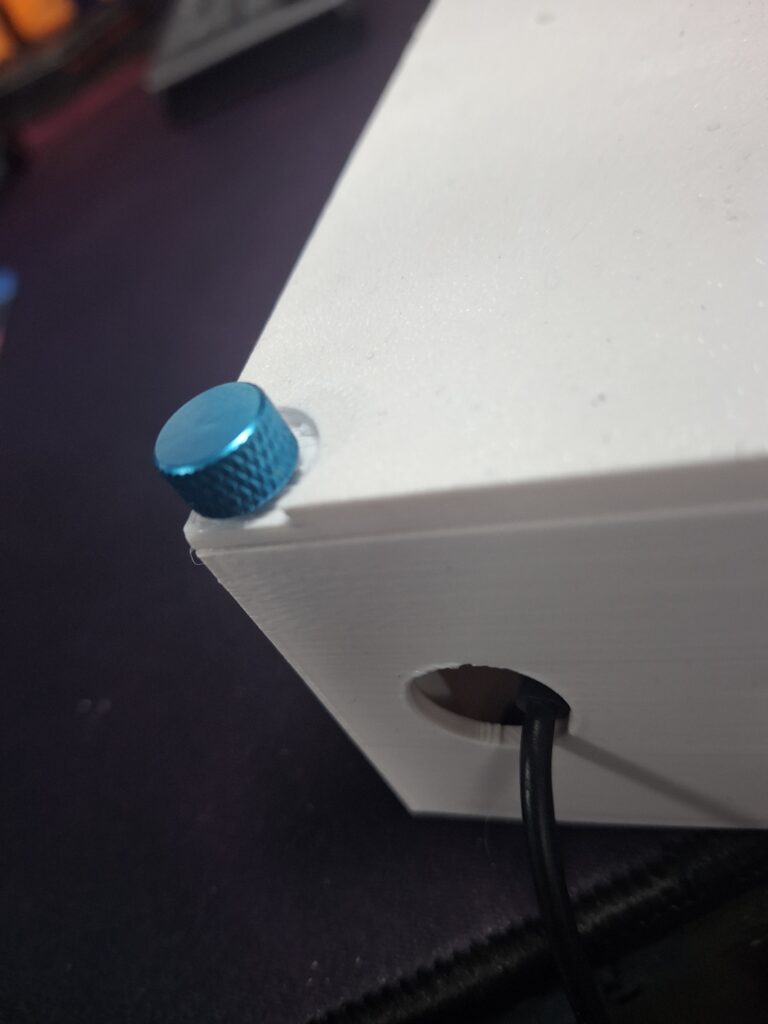
So i order them, only to find out they are not the same 8mm as my existing screws…..bugger!!!!!More model changes
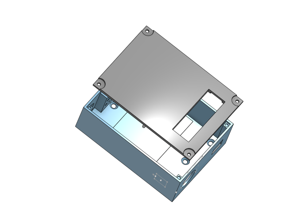
So to get around this issue, opted for some inset sections to allow the screws to better grip the inserts in the base.
Worked a treat
Looks great, now to get the greenhouse built this weekend and then get it installed in place.
Components Used
Not affiliate links